

Source: From Red Pine and public information, synthesized by U Study Online
Ⅰ. What is Fiber Jumper ?
Fiber jumper, also known as the jumper fiber or optical fiber patch cord, is the jumping of optical fibers to connect the two ends of the network equipment, including the following three scenarios:
1. the equipment and equipment between the fiber optic patch connection.
2. the equipment and fiber patch panel fiber patch connection.
3. fiber patch panel and fiber patch panel fiber patching.
Ⅱ. Classification of Optical Fibers
a. By fiber optic interface: divided into LC, FC and SC. combined together the two ends of the fiber optic are: FC-FC, SC-SC, LC-LC, FC-SC, FC-LC, SC-LC, a total of six types.
LC is a 1.25 mm ferrule in engineering plastic with small square connectors.
FC is a 2.5 mm ferrule made of metal with a round threaded connector.
SC is a 2.5 mm ferrule in engineering plastic with a standard square fitting.
b. By fiber length: 1.5 m, 2 m, 3 m, 5 m, 10 m, 15 m, 20 m, etc.
c. By fiber usage: LC interface is commonly used in equipment; FC interface is commonly used in ODF to connect remote cores; SC interface is commonly used in ODF and equipment.
Ⅲ. Fiber Jumper Placement Principles
With so many types of fiber, it is inevitable that they cannot be placed at random. In order to facilitate future operations and maintenance, the following principles need to be met when jumping fibers:
1. Fiber, must meet the ODF and equipment of the fiber neatly, wiring beautiful, easy to operate, less space occupied by the principle.
2. The length of the patch fiber must be mastered within the 500mm remaining length.
3. Insufficient length of the patch fiber shall not be used, and the use of flanges to connect two sections of patch fiber is not allowed.
4. Each fiber jumper should ensure that the radius of curvature of each place is greater than 400mm.

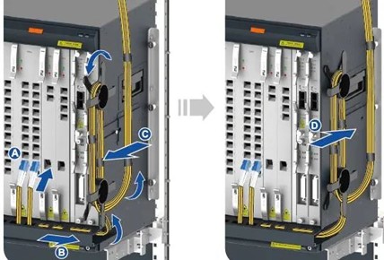
5. Fiber jumping, first one end of the fiber to access the equipment port, the other end from the wiring slots to go fiber, pull out the tray fiber frame will be wrapped around the excess fiber into a circle, cloth on the tray fiber frame, and fiber ties wrapped and pushed into the tray fiber frame, and then the other end to access the equipment or ODF rack.
6. General requirements for fiber alignment:
①For the fiber on the go, it should be under the outside of the ODF frame, choose the most suitable tray fiber column for the remaining fiber, and go up the fiber on the inside of the ODF frame, horizontally on the lower edge of the ODM, vertically up to the corresponding terminal.
②A patch fiber is only allowed to go up once (along the outside of the ODF frame) and up once (along the inside of the ODF frame) in the ODF frame, on one tray fiber column, and it is strictly forbidden to twist, cross or hang between several tray fiber columns, i.e. no fiber should be twisted along the top edge of each tray fiber column.
③The site specifics should be tied after tidying up the fiber jumpers at the beginning of the adaptation regulations.
④All fiber jumpers must be laid inside the ODF frame, and the laying and flying of wires outside the frame is strictly prohibited.
⑤For emergency use of extra-long fiber jumpers should be hung on the inner fiber tray in accordance with the rules and must not have an impact on future fiber jumpers.
7. Tray fiber, the same fiber is strictly prohibited in more than one tray fiber rack cross-winding.
8. Across the cabinet of the fiber, across the cabinet to use sleeves to protect the fiber, to avoid the fiber is extruded by other cables, with wiring frame to be placed in the wiring frame.
9. The optical fiber connection must not be pulled too tightly and the joint is at right angles.
10. All optical fibers must be placed in the wiring trough, off-rack placement or flying wires are strictly prohibited.
11. Insufficient length of optical fiber shall not be used, do not allow the use of fiber optic adapters to connect two sections of optical fiber, to avoid increasing the fiber decay.
12. When inserting optical fibers, clean the end face of the fibers (fiber optic connectors). It is forbidden to touch the end face of the optical fiber directly by hand or to allow the end face of the optical fiber to touch objects in the production environment.
13. When connecting optical fibers, the fiber optic connector should be inserted vertically into the optical interface, avoiding angled insertion. The entire fiber optic connector should be inserted into place. Commonly used SC and LC connectors will hear a "pop" sound to indicate that the connection is in place.
14. It is strictly forbidden to pull the optical fibers with force, which may easily cause cracking of the fibers and connectors.
15. Twisted fibre optic cable is strictly prohibited, to avoid possible twisting of fiber optic cable, should follow the natural slack state of the fiber optic for reeling.
Note: The copyright of this article is owned by the original author, if there is any infringement, please contact to inform, the article will be removed. The content of this article has been slightly abridged.

